
FGD-Suspension Separating Method
- Less one-off investment
- High dust collect efficiency
- Low rate of maintenance
- Long service life of filter bag

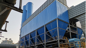
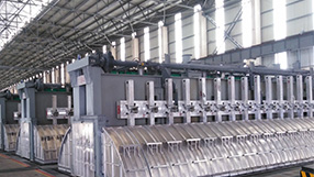
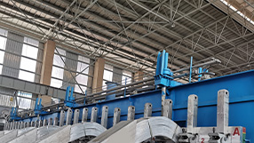
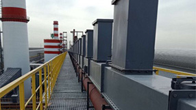
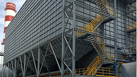
New Type of Dust Collector (low-energy consumption)
- Cost saving
- Investment saving
- Operating cost reducing
Bake-oven Fume Treatment Center
- High lifting capacity
- Stable lifting
- Long service life
- Convenient maintenance and operation
Denitration system
- Less one-off investment
- High dust collect efficienc
- Low rate of maintenance
- Long service life of filter bag
Anode Jacking Device (Triangle Plate)
- Less one-off investment
- High dust collect efficiency
- Low rate of maintenance
- Long service life of filter bag
Screw Lift
- Less one-off investment
- High dust collect efficiency
- Low rate of maintenance
- Long service life of filter bag
Super Dense Phase Conveying System
- Less one-off investment
- High dust collect efficiency
- Low rate of maintenance
- Long service life of filter bag


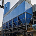
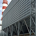

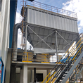


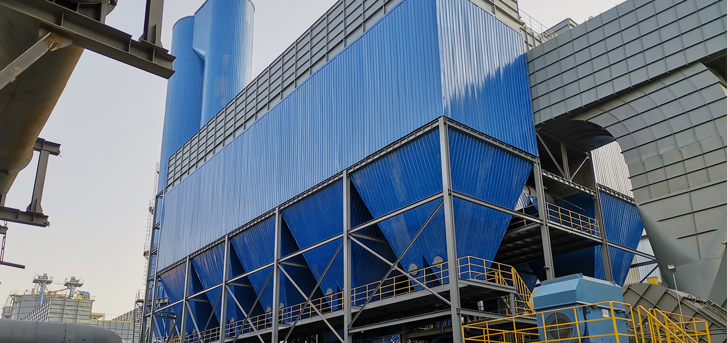
New Type of Dust Collector (low-energy consumption)
New Type of Dust Collector (low-energy consumption)
With the low-pressure pulse dust removal mode, the dust collector is equipped with a broad type fluorine absorption device and a bidirectional turbulent reactor in its interior and a new multi-point reactor in its exterior. In the exterior reactor, the alumina injection can easily cover the cross-sectional area of the whole reaction channel.
The HF gas is almost all absorbed by alumina after gas passing through the reactor, and the fluorine absorption efficiency reaches over 99.8% (the reactors are all patented products of our company, and have been widely provided to many smelters at home and abroad in their gas purification equipment with satisfactory results). Since the dust collector is equipped with three reactors improving the defluorination efficiency greatly, it is not required to add extra large amount of circulating alumina to absorb fluorine again. In this way, the dust concentration at the inlet of the dust collector is greatly reduced, so does the resistance of filter bag. The differential pressure of the conventional dust collector is generally about 1500pa, while that of the dust collector with this technology is reduced to about 1000Pa, which saves about 500pa.
As the resistance of the dust collector is greatly reduced, the negative pressure at the upper end of the pot is significantly increased. The negative pressure at the outlet of the upper end of the pot can reach - 300 ~ - 450pa (the pressure can be adjusted). In this way, the gas collection efficiency of the pot is significantly improved, the fugitive emission of fluorine and dust in the potroom is reduced, and the recovery rate of fluorine and dust is increased.
The special structure of our company's bag filter makes the flue gas change its movement direction when entering into the inside of the filter, converting the kinetic energy of the air flow into potential energy. We have set a lower design wind speed for the gas entering into the filter so as to reduce the operating pressure difference of the filter, which is 500pa less than that of the filters of other manufacturers in the same industry under the condition of the same filtering area, thus the energy consumption is reduced by 20%.
2.2 Equipment Features
2.2.1Dust Collector Composition
Dust collector is mainly composed of: clean air maintenance room, middle box, orifice plate, blowing pipe, air-manifold, pulse valve, filter bag, bag cage, lower box, hopper, broad type fluorine absorption device, bi-directional turbulent reactor, air inlet, air outlet etc.
2.2.1.1 Clean Air Maintenance Room
The clean air maintenance room is the operation space for maintenance and replacement of filter bags and bag cages. Its structure shall have certain strength to keep the natural ventilation at the top of the dust collector in good condition, and the design of canopy shall meet the requirements of local rainfall.
The top of the bag filter is equipped with an electric monorail crane with a lifting capacity of 1.5T, which is used to lift the maintenance cover plate, replace the filter bag, and lift the filter bag and other accessories from the ground to the top platform of the filter. The total lifting height meets the lifting requirements.
2.2.1.2Middle Box
The function of middle box is used to fix filter bags, bag cage, blowing pipe, pulse valve and air manifold. It is the core part of filter, since its precision and structure will directly influence filter working life and performance index of the bag filter. Normally the machining of middle box are done in specialized mold. Welding line of the box adopts 100% seal welding. In order to make sure welding line quality, magnetic powder detector is used to detect welding line to see if there is any deficiency like sundry, pore, crack, etc.
Middle Box
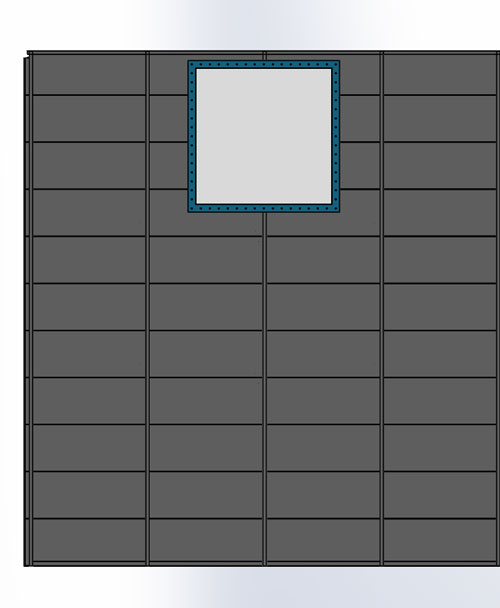
2.2.1.2.1 Orifice Plate
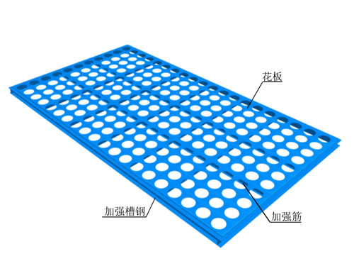
Orifice plate
Orifice plate is used to fix filter bag, its processing quality will directly influence bag working life, dust emission index and filter working life. For material of orifice plates, our company select Q345B 8mm thick steel plate, and all aperture is cut by laser cutting machine with aperture error ≤0.06㎜ , and aperture horizontal and vertical error ≤0.15㎜. After laser cutting, the area around aperture is smooth without burr, making sure no damage to filter bag so as to lengthen bag working life. 10# channel steel is placed around the plate bottom to reinforce the plate, and there are multiple 100×80 flat steel stiffeners horizontally and vertically with an interval length no more than 480mm. There is 12# I steel in middle of the plate to increase its strength and avoid deformation. The levelness of orifice plate is critical. Its flatness deviation is not more than 1‰ of the plate length. When pulse valve is blowing, the maximum skipping range of orifice plate is ≤1.0㎜. Weld joint is 100% seal welding, and detected by magnetic particle testing to see if there is deficiency like sundry, pore, and crack etc, so as to make sure the welding line is with good quality. After sand blasting and derusting, the surface of the orifice plate shall be well treated to prevent rust.
2.2.1.2.2 Blowing Pipe

Blowing Pipe
Blowing air flow of filter bag is jetted inside the bag through a nozzle on blowing pipe, so its quality is directly related to dust removal result and bag working life. For a good blowing system, air flow blowing from each nozzle is equal, jetting resistance is small , air flow jetted is concentrated, air injecting flow around nozzle is big, dead zone above filter bag is small, deformation of blowing pipe is small, and skipping range while blowing is small. There are multiple nozzles on each blowing pipe (Ф89㎜ dia). Nozzle shape adopts minimum resistance structure, distance error between nozzles <0.1㎜, and accumulative error is not more than 0.4mm, perpendicularity between nozzle and blowing pipe is not more than 0.1mm,the error between nozzles is no more than 0.1mm every linear meter, and the accumulative error is not more than 0.2mm , dead zone length above bag is ≤90㎜, the maximum skipping range of blowing pipe ≤1㎜, number of fixation for each blowing pipe is 3, injecting air flow is 3.3 times of nozzle air flow. Blowing time between 0.1~0.3s adjustable, blowing cycle 2~60minutes adjustable, blowing pressure 0.30~0.40Mpa, one-time gas emission for each pulse valve is 0.25~0.35Nm³. The deformation is not more than 0.2mm every linear meter. The blowing pipe is easy for maintenance and has good interchangeability.
Our blowing pipe is made by specialized mold. The seamless steel pipe is fixed on the special mould multi-stage combined drilling machine, and all the holes on the blowing pipe are processed once by the multi-stage combined drill. The welding of nozzle and blowing pipe is carried out in the mold through argon arc welding with 100% air tightness. After the nozzle is fixed, vertical center line of the nozzle and orifice plate shall be on the same line with error no more than 0.1mm.
2.2.1.2.3Air-manifold
Air-manifold
Air-manifold is the main energy storage device of low pressure pulse filter, the energy storage device function is closely related to dedusting result of filter bags, as its volume, structural type and material are all factors that influence dedusting effect, system cleaning efficiency and equipment working life. There are 2 air-manifolds on each filter (tandem connection). The maximum working pressure is 0.8Mpa, test pressure is 1.2Mpa. Air-manifold structure is cylinder shape, and there are 40 pulse valves on each air-manifold. On the bottom of air-manifold, there is blow-down valve installed which can discharge sundries in air-manifold regularly.
Features of air-manifold:
①Cylinder shape structure is with small deformation. When pressure inside air-manifold is jumped, deformation is almost zero
②High strength, long working life, made of seamless steel pipe, no deformation under 0.8Mpa air pressure. Anti-corrosion and has long operating life.
2.2.1.2.4 Pulse Valve
The specification of pulse valve is 3 ", its features are:
1) the diaphragm has strong fatigue resistance, high temperature resistance (150 ℃), impact resistance, aging resistance, and operation times ≥ 1.5 million.
2) The operation resistance is small, the air intake is large, and the air volume for each injection is not less than 0.25m3.
3) High sensitivity, action time ≤ 0.1s.
4) High strength, nice appearance, with shell die casted from aluminum alloy, small deformation, beautiful surface and convenient loading and unloading.
2.2.1.2.5 Filter Bag
The filter bag is the key part of the dust collector, which is directly related to whether the dust emission index is up to standard, whether the operation resistance of the dust collector is up to standard, and whether it can meet the fugitive emission flue gas recovery standard of potroom. In many years of production practice, we summarized the physical performance and chemical changes of the filter bag in the operation process, and put forward a set of new technical indicators of the filter bag, which greatly improved the performance of the filter bag. In order to ensure the purification efficiency, the filter bag is designed with polyester aramid composite needled felt, which is treated with chemical vapor to improve the temperature resistance, so that the filter bag can be used at 150 ℃ for a long time, with a instant temperature resistance of 160 ℃.
Processing characteristics of filter cloth:
A、 The filter bags have high porosity, good air permeability and high purification efficiency;
B、The surface of the filter bag is treated with singeing technology and high pressure polishing, which makes the surface smooth and flat, with small adhesion, and achieve the best dust cleaning effect;
C、The filter bag selected in this project can ensure long-term stable operation under 150 ℃, guarantee service life of more than 3 years, and the change of air permeability is small under the allowable service temperature of the filter bag;
D、In order to increase the tensile strength, the filter bag has been applied temperature resistant shaping treatment to have a tensile strength 1.35 times higher than that of the ordinary filter bag.
E、The connection between the filter bag and the orifice plate is is very critical. When the filter bag bears 70 kg downward pull, the filter bag and the orifice plate are not disconnected, and have good sealing performance. At their joint, the filter bag will not be damaged under the impact of the changing air flow, and it can work reliably for more than 4 years. 3J53 material is used as the elastic circlip for the upper sealing of the filter bag. Under the condition of 190 ℃ temperature change, the elastic modulus is unchanged, which can effectively maintain the sealing performance of the filter bag for a long time with good interchangeability.
F、 The longitudinal seam of the filter bag is connected in the form of hot-melt, which has the advantages of vertical longitudinal of the filter bag and deformation ≤ 1mm.
2.2.1.2.6Bag Cage
Bag cages are used to support filter bags. Special automatic production line is used to finish the bag cages. Firstly, the steel bar is cold-drawn twice in the cold-drawing machine into a steel wire of φ3.8㎜.
In the process of cold drawing plus the force of swirling, the steel wire becomes hard and elastic. Under the action of aerodynamic force, the cold-drawn steel wire automatically enters the high-frequency hot welding machine. At the same time, the fixed ring of the bag cage also enters automatically. Under the control of PLC, the whole welding process of each bag cage can be completed within about 30 seconds. The solder joint of the finished bag cage is firm, the surface is smooth and the radial bearing force of the bag cage is≥ 600N.
Bag cage self-locking clamp joint: This design divides the bag cage into two parts, each part is half the length of the filter bag. The two self-locking clamp joints are very convenient, reliable and smooth, without damage to the filter bag. The self-locking clamp joint is made of 2mm cold rolled steel plate and stamped with a die. The contact surface of the joint has high smoothness, firm contact, small clearance, and the error of verticality is less than ±1㎜. Meanwhile, the contact part has a self-locking chuck. When the contact surface and the tightness are ready as per requirement, the contact part will be locked in order to prevent the bag cage from falling off and damaging the filter bag during the operation of the dust collector.
While supporting filter bag, there will also be friction between bag and cage. Filter bag can be damaged easily if design is not proper. With site operation experience over the years, we decided to have transitional contact mode for connection between bag and cage to reduce excessive friction in between. The finished product of filter cage is 100% exchangeable.
2.2.1.3 Lower Box
The lower box is the space for the filter bag, which occupies the largest volume and the highest height in the whole dust collector, usually 6-7m in height. Therefore, the mechanical strength of the lower box must be considered first.
The lower box shell is made of 5mm thick Q235B steel plate. There are several channel steels as supporting columns in the longitudinal direction, and several 80 × 8 flat steels as reinforcing ribs in the transverse direction. The deformation of the box shell under the pressure of ± 5000Pa is not more than 2mm. The welds are 100% sealed welding. The welds are tested by magnetic particle detector to see if there are inclusions, air holes, cracks and other defects in the welds, so as to ensure the quality of the welds.
Lower Box
2.2.1.4 Hopper
The hopper is a container for collecting aluminum fluoride. The design angle of four end faces of the hopper is 45 ° ~ 55 °. The hopper is made of 5mm thick Q235B steel plate, and the reinforcing rib is made of 100 × 8 flat steel. The volume of hopper is about 54m3. The dust collector can continue to work even in extreme case like blocking of returning fluoride alumina. When the hopper is full of fluoride alumina, the deformation of the four end faces of the hopper is no more than 0.3mm for each extended meter. The hopper is equipped with a Φ 500 manhole, which is convenient for the operator to maintain and repair. The sealing performance of manhole is 100%, and the opening times is ≥ 3000 times without leakage. The welds are 100% sealing welding, and magnetic particle detection is applied for weld test to see whether there are inclusions, air holes, cracks and other defects in the weld, so as to ensure the quality of the weld.
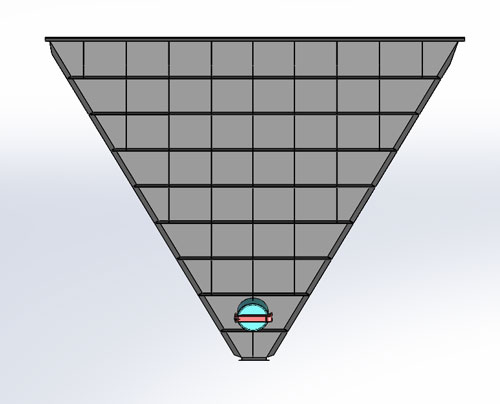
Hopper
2.3 Deflector
In order to prolong the service life of the elbow in the reaction channel, we optimized and improved the structure of the elbow. First of all, the material of the large elbow deflector is changed to the wear-resistant Q345B material, which improves its wear-resistance in essence; secondly, we add deflectors on the wear surface of the direct impact of flue gas on the inner wall of the large elbow. With this structure, the flue gas entering the large elbow is evenly distributed under the function of the deflector, which greatly extends the service life of the elbow.
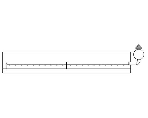
2.4 Technical Features of Airslide:
2.4.1 Airslide configuration and component description
Each airslide is equipped with end flange feed hole , quick opening hole, sight glass, exhaust hole, etc. Each airslide air chamber is equipped with air inlet, inspection hole and fabric.
2.4.2 The airslide is made of Q235B 3mm thick steel plate. The inner wall of the airslide is coated with wear-resistant coating. The service life of the airslide is 15 years.
2.4.3Airslide flange
The airslide flange is made of Q235B, laser cut with flatness error no more than 0.1mm, hole diameter φ 11mm( error no more than 0.1mm), hole distance error no more than 0.1mm. The flange and the airslide are connected by full girth welding, 100% sealing. The perpendicularity of the flange to the airslide is not more than 0.05. The surface of flange is sandblasted and polished.
2.4.4 Fabric
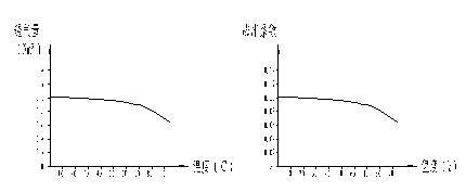
The thickness of the fabric is 6mm, the working temperature is ≤ 150 ℃, the tensile strength is > 450kg / cm2, the elongation at break is ≤ 6%, and the air permeability is 1.2-1.5m3/m2 · min. When the air pressure is 1200pa, the relationship between the air permeability and the temperature is shown in the left figure below; when the air temperature is 20 ℃, the relationship between the expansion coefficient and humidity of the fabric is as the right figure below.
The fabric shall not sag in the airslide. When the thickness of alumina is 200mm, the sagging of fabric shall be ≤ 1.2mm. When there is no alumina in the airslide material chamber, the air chamber pressure shall be 250mm water column height, and the swelling of the fabric shall be ≤ 1.5mm. To meet the above requirements, the assembly of the fabric and the airslide shall only be carried out after 40 minutes of fabric humidifying in a special container with temperature controlled at 50 ℃± 2 ℃, and the duration of the assembly shall not be more than 15 minutes.


